HI EC,
This is all about Servo Tuning so it is appropriate for our forum.
What you describe sounds a lot like your servo is dominated by l gain (Integrator). The Integrator "Integrates" the error so that the commanded motor torque accumulates based on how much and how long the error has persisted. The beauty of I gain is that it guarantees an average error of zero. With any I gain at all It is impossible to have even a small error for a long time. Eventually the error will accumulate enough torque to make a correction. The magnitude of the I gain will determine how quickly the torque ramps up to make the correction. The disadvantage of I gain is that it is very destabilizing. It will cause the torque (acceleration) to continue to increase until
the target position is reached. The analogy in a car would be to reduce the gas as you approach a stop sign but not even begin to brake. The only way this will work is if there is a lot of drag (friction) or damping (D gain).
The big overshoot when you release the motor shaft is often referred to as "Integrator Wind Up". If the motor shaft is forced and held such to cause an error the integrator will continuously accumulate the error much like winding a spring. If the
shaft is suddenly released it will overshoot the target position violently. Most systems have a limit on how much the Integrator can ramp up (In KFLOP this is the Max Limit Integrator Parameter MaxI). This value should be large enough to correct any persistent error under normal conditions but will then limit the amount of accumulation under abnormal conditions where the servo is prevented from reaching the target for some reason.
It seems your system is operating mainly using a tiny amount
of I gain. This will result eventually in zero error, but the dynamics will be terrible. Increasing the I gain would make the response quicker but most likely make the system unstable.
A common procedure for Servo Tuning is to first set the I gain to zero and obtain the best dynamic performance you can with P, D and Filters. Then later add a small amount of I gain to reduce small persistent errors. With only P and D gains a small error (multiplied by P) may generate only a small amount of output
(torque) which is insufficient to overcome friction and cause any motion. In this case the small error may persist forever. The Integrator can be used to overcome this.
HTH Regards TK
| Group: DynoMotion |
Message: 10312 |
From: Tapio Larikka |
Date: 10/11/2014 |
| Subject: Re: do my servos behave normally? [OT] |
Hi Eric,
Your symptoms sound alot like what I had when I ran
my mill with Mach/Pport&Step/dir.
I think your last sentence sums the problem and
solution. It's like you have an orchestra where conductor hands out notes and
sits back expecting everyone
to play the same tune without
guidence.
I have two mills w/ KFlops wired closed loop analog
servos, totaling 7 servo axis and only one axis has slightly similar behavior,
but only when I
turn it with 10" wrench, as it's the spindle drive
;-).
My suggestion is that you wire the encoders to
KFlop and config the system to closed loop operation. Let the conductor conduct,
you already paid for it.
Rgds,
Tapio
| Group: DynoMotion |
Message: 10319 |
From: ericncn |
Date: 10/12/2014 |
| Subject: Re: do my servos behave normally? [OT] |
Tom, Tapio, thank you!
Your answers imply that my servo behavior isn't good. I really didn't
know (that's why I asked); I had already followed the drives manual's
tuning instructions and I believed that part was OK... now I know that I
have to tune my drives better.
Tom, what you wrote makes sense. Set the I gain to zero, tune the other
parameters first, then increase the I gain. This wasn't very clear in
the manual and I was doing all the tuning without zeroing "I" first.
This is the tuning manual:
http://granitedevices.com/assets/files/Tuning_manual.pdf
and, just in case you are curious, these are the drives:
http://granitedevices.fi/assets/files/vsd-e_160_manual.pdf
If you go to page 24 and 25, you see these drives use natively a "PIV"
control and provide a "PID" control as an (emulation?) only.
I though it was better to stick to the native "PIV" to get better results.
Anyway, I don't want to abuse of your time.
Now that I know what's my problem, I'll try ask the drive manufacturer
first, then I see there's plenty of information on the Internet on the
"servo tuning" subject.
Hopefully I should be able to sort it out
Thank you again
EC
---In DynoMotion@yahoogroups.com, <tk@...> wrote : HI EC,
This is all about Servo Tuning so it is appropriate for our forum.
What you describe sounds a lot like your servo is dominated by l gain (Integrator). The Integrator "Integrates" the error so that the commanded motor torque accumulates based on how much and how long the error has persisted. The beauty of I gain is that it guarantees an average error of zero. With any I gain at all It is impossible to have even a small error for a long time. Eventually the error will accumulate enough torque to make a correction. The magnitude of the I gain will determine how quickly the torque ramps up to make the correction. The disadvantage of I gain is that it is very destabilizing. It will cause the torque (acceleration) to continue to increase until
the target position is reached. The analogy in a car would be to reduce the gas as you approach a stop sign but not even begin to brake. The only way this will work is if there is a lot of drag (friction) or damping (D gain).
The big overshoot when you release the motor shaft is often referred to as "Integrator Wind Up". If the motor shaft is forced and held such to cause an error the integrator will continuously accumulate the error much like winding a spring. If the
shaft is suddenly released it will overshoot the target position violently. Most systems have a limit on how much the Integrator can ramp up (In KFLOP this is the Max Limit Integrator Parameter MaxI). This value should be large enough to correct any persistent error under normal conditions but will then limit the amount of accumulation under abnormal conditions where the servo is prevented from reaching the target for some reason.
It seems your system is operating mainly using a tiny amount
of I gain. This will result eventually in zero error, but the dynamics will be terrible. Increasing the I gain would make the response quicker but most likely make the system unstable.
A common procedure for Servo Tuning is to first set the I gain to zero and obtain the best dynamic performance you can with P, D and Filters. Then later add a small amount of I gain to reduce small persistent errors. With only P and D gains a small error (multiplied by P) may generate only a small amount of output
(torque) which is insufficient to overcome friction and cause any motion. In this case the small error may persist forever. The Integrator can be used to overcome this.
HTH Regards TK
| Group: DynoMotion |
Message: 10343 |
From: ericncn |
Date: 10/20/2014 |
| Subject: Re: do my servos behave normally? [OT] |
|
I want to publicly thank Tom for being so helpful!
A few words were more useful than the drive manufacturers' own manual... by zeroing the "I" gain first, I could increase the P gain much more then before and after that, surprisingly, even the I gain itself could be raised more!
My servos now work better but still not perfect. They have a tendency to vibrate that prevents me raising the gains enough to make them really stiff.
I believe this is due to my servos being small for the machine, and coupled direct drive (1:1). An approximate computation of the "load inertia" ratio results in large numbers hence it is probably useless to insist tuning the parameters if I don't add a reduction ratio before.
Experts correct me if I'm wrong.
I would not want to take the hassle to do all the conversion to belts, pulleys etc. and then discover it had nothing to do with the vibrations.
Maybe I could just disconnect the motors from the lead screws and try the tuning with no load connected to the motors?
If the load-less motors could be tuned to be stiff and vibration-free at the same time, could that demonstrate that the issue is actually a too large load inertia ratio?
And that it could be cured by adding a reduction ratio?
Thank you a lot
EC
|
|
| Group: DynoMotion |
Message: 10350 |
From: Tom Kerekes |
Date: 10/20/2014 |
| Subject: Re: do my servos behave normally? [OT] |
Hi EC,
Thanks for that.
I doubt if the tuning issue is related to small motors or direct drive. Although it is hard to say for sure. The peak acceleration of the system and the servo stability of the system are two entirely different things. Bigger motors and lower gearing are likely to allow higher acceleration but are likely to basically make the system more complex dynamically, slower to respond, and less stable.
Moment of inertia increases with the 5th power of "size" !! (a 2 inch cube is 32X harder to spin up than a 1 inch cube). So generally if you want to make slow-powerful forces use a big motor. If you want to make fast-small forces use a small motor.
Load inertia ratio of 1:1 will allow the highest acceleration. Basically the amount of power a motor can
provide is proportional to its speed. So if it is geared too high the motor generates only a small power but most all of it goes into the load. If it is geared too low it generates a lot of power but most all of it goes into accelerating the motor rather than the load. Turns out the optimum is when half of the power goes into accelerating the motor and half into the load. But again designing for large forces to the load, and being able to quickly apply forces to a load, are often contradictory.
A Bode Plot is one of the most useful tools to help understand the dynamics of a system.
Removing the load to tune the servos is probably not very useful. A lot changes when the load is connected. Unless you just want to do that as an exercise to see what is possible with no load knowing everything will change when loaded.
HTH Regards TK
| Group: DynoMotion |
Message: 10445 |
From: ericncn |
Date: 10/31/2014 |
| Subject: Re: do my servos behave normally? [OT] |
Hi Tom, yes, the purpose of tuning the motors after disconnecting the load would have been to verify whether the vibrations depend on the load, or not. Anyway, now my Kflop is finally reading the encoder of one axe and I can use the Bode Plot and Step Response screens. I guess I now have to study all the related material on Kflop manual before doing the next move. Or, is there any thread on this newsgroup that discuss this and that I can use as a quick start guide? Thank you EC ---In DynoMotion@yahoogroups.com, <tk@...> wrote : Hi EC,
Thanks for that.
I doubt if the tuning issue is related to small motors or direct drive. Although it is hard to say for sure. The peak acceleration of the system and the servo stability of the system are two entirely different things. Bigger motors and lower gearing are likely to allow higher acceleration but are likely to basically make the system more complex dynamically, slower to respond, and less stable.
Moment of inertia increases with the 5th power of "size" !! (a 2 inch cube is 32X harder to spin up than a 1 inch cube). So generally if you want to make slow-powerful forces use a big motor. If you want to make fast-small forces use a small motor.
Load inertia ratio of 1:1 will allow the highest acceleration. Basically the amount of power a motor can
provide is proportional to its speed. So if it is geared too high the motor generates only a small power but most all of it goes into the load. If it is geared too low it generates a lot of power but most all of it goes into accelerating the motor rather than the load. Turns out the optimum is when half of the power goes into accelerating the motor and half into the load. But again designing for large forces to the load, and being able to quickly apply forces to a load, are often contradictory.
A Bode Plot is one of the most useful tools to help understand the dynamics of a system.
Removing the load to tune the servos is probably not very useful. A lot changes when the load is connected. Unless you just want to do that as an exercise to see what is possible with no load knowing everything will change when loaded.
HTH Regards TK
|
|
| Group: DynoMotion |
Message: 10446 |
From: Tom Kerekes |
Date: 11/1/2014 |
| Subject: Re: do my servos behave normally? [OT] |
Hi EC,
You might want to spend some time in the Time Domain (Step Response Screen) first to observe your "vibrations" and such first.
Then please read the help on the Bode Plot:
Here is an example with great performance (100Hz bandwidth)
HTH Regards TK
From: "ericnc@... [DynoMotion]" <DynoMotion@yahoogroups.com>
To: DynoMotion@yahoogroups.com
Sent: Friday, October 31, 2014 6:12 PM
Subject: Re: [DynoMotion] Re: do my servos behave normally? [OT]
Hi Tom,
yes, the purpose of tuning the motors after disconnecting the load would have been to verify whether the vibrations depend on the load, or not.
Anyway, now my Kflop is finally reading the encoder of one axe and I can use the Bode Plot and Step Response screens.
I guess I now have to study all the related material on Kflop manual before doing the next move.
Or, is there any thread on this newsgroup that discuss this and that I can use as a quick start guide?
Thank you
EC
---In DynoMotion@yahoogroups.com, <tk@...> wrote :
Hi EC,
Thanks for that.
I doubt if the tuning issue is related to small motors or direct drive. Although it is hard to say for sure. The peak acceleration of the system and the servo stability of the system are two entirely different things. Bigger motors and lower gearing are likely to allow higher acceleration but are likely to basically make the system more complex dynamically, slower to respond, and less stable.
Moment of inertia increases with the 5th power of "size" !! (a 2 inch cube is 32X harder to spin up than a 1 inch cube). So generally if you want to make slow-powerful forces use a big motor. If you want to make fast-small forces use a small motor.
Load inertia ratio of 1:1 will allow the highest acceleration. Basically the amount of power a motor can
provide is proportional to its speed. So if it is geared too high the motor generates only a small power but most all of it goes into the load. If it is geared too low it generates a lot of power but most all of it goes into accelerating the motor rather than the load. Turns out the optimum is when half of the power goes into accelerating the motor and half into the load. But again designing for large forces to the load, and being able to quickly apply forces to a load, are often contradictory.
A Bode Plot is one of the most useful tools to help understand the dynamics of a system.
Removing the load to tune the servos is probably not very useful. A lot changes when the load is connected. Unless you just want to do that as an exercise to see what is possible with no load
knowing everything will change when loaded.
HTH Regards TK
|
|
| Group: DynoMotion |
Message: 10447 |
From: ericncn |
Date: 11/1/2014 |
| Subject: Re: do my servos behave normally? [OT] |
Hi Tom, I've spent some time in the Step Response Screen and it seems me that the system, AS IS (servo drive set in position mode, driven by Kflop in quadrature mode) (channel 24) has a quite good response to the step command, and if I put it in "CL step" mode, it only gets worse for any value different than zero that I give to P, I and D (starts vibrating/oscillating/resonating violently). Which leads me to a general question before I go on messing the system and break something: should I go on studying it AS IS ? Or should I reconfigure it before? It looks me that the Kflop PID conflicts with the PIV internal to the motor drive, that was previously tuned "as hard as possible" meaning it tends to make sound when holding position. Should I lower the gains in the motor drive before going on? Also how do I tell Kflop I have servos and not steppers? It seems that the "stepper " and "CL step" are the only modes that work. If I select anything else the motors doesn't move. Thank you EC ---In DynoMotion@yahoogroups.com, <tk@...> wrote : Hi EC,
You might want to spend some time in the Time Domain (Step Response Screen) first to observe your "vibrations" and such first.
Then please read the help on the Bode Plot:
Here is an example with great performance (100Hz bandwidth)
HTH Regards TK
|
|
| Group: DynoMotion |
Message: 10448 |
From: Tom Kerekes |
Date: 11/1/2014 |
| Subject: Re: do my servos behave normally? [OT] |
Hi Eric.
I assume you meant to say a "Move" command on the Step Response Screen?
What you are trying to do is a bit unusual. You are closing a position loop around another position loop using the same encoder. It doesn't really make much sense to do this. The drive should be able to close the loop just as well as KFLOP could - unless the drive is missing some capability like filtering or doesn't have as good of tools to find the correct parameters in the first place.
Also closing one loop around another to try to improve it is complex. An analogy might be something like this: Imagine a drunk person is driving a car weaving down the road. A simple approach would be to put them to sleep and let you drive. But that's not what you are doing. Rather what you doing is more like leaving them drive, but then watching how they drive down the road and adjusting where they see the lines on the road, to attempt to keep them more centered on the
road. You need to compensate for both the characteristics of the car as well as the characteristics of the drunk driver. If they are slow to react to commands it makes things very difficult if not impossible.
But one thing that usually does work is to correct slow gradual drifts. If the drunk driver persistently drives on the shoulder of the road, then you could gradually shift the lines on the road over a
few feet to improve things. But quickly shifting lines would be likely to cause the drunk driver to over correct and begin weaving.
The I gain factor can be used for this. It observes and accumulates how much and for how long the error has been on one side and shifts the target accordingly. You probably have just added too much I gain. I gain is usually a small number like 0.0001. There will
always be some number where the system is still stable although it may not help much in correcting errors quickly. If the drive has effective Integrator gain then the average error should already be zero.
So I think your focus should first be to determine how well your drive is performing on its own (with KFLOP PID parameters zero). You say it "has quite good response" so I'm not
really sure what you are doing this for. Post some plots so we can see what you mean. What are the following errors and at what velocities and accelerations? You should also tell us what type of machine this is, what the resolution is, and what your expectations are.
Then you might perform a Bode Plot (again with KFLOP PID parameters zero). A Bode Plot is essentially testing the system by giving it a test track that curves
back and forth at different frequencies. One could characterize the performance by testing on hundreds of different race tracks each with a different frequency of curves, but that would take a long time. Instead we use a test track with all manner of different random curves. The math then basically determines how the system did where the frequency was this and that. It then analyzes the data to see how well it follows each frequency and plots it on a graph. Generally systems follow slow gradual curves very accurately. As the curves become tighter and faster the errors will become larger. Basically where a Bode plot shows high gain this indicates it did very well. Where the gain is very small (less than 1 which is the same as less than 0db) the system hardly followed the path at all. The first frequency where the gain drops to 0db is what is commonly referred to as the bandwidth of the system. This is
where about half of the error is being corrected - not very good, but still much better than nothing. So bandwidth is a good figure of merit to describe how dynamically responsive a system is.
As pointed out in the help files that in order to get a Bode plot that is actually meaningful it must be stimulated by a reasonable amount. The stimulation amplitude is basically how much the curves in the road go back and forth. Theoretically a perfect system with infinite available power and
infinite resolution would have the same dynamic response regardless of the amplitude of the curves and the Bode plot would come out the same. But in the real world things are not like that. Imagine curves too large where the car steering wheel hits the stops left and right (amplifier saturation) then the result will be incorrect and meaningless. If the curves are too tiny then it will be difficult to even measure if the car is following them (encoder quantization error). Normally KFLOP's stimulation output is something like motor current so it is easy to see how hard we are driving the system. But unfortunately in your case the output is position and the motor current is in the drive which we can't see. This makes it extra hard to see if we are stimulating the system in a reasonable manner.
Let me know how much of this makes sense. Regards TK
From: "ericnc@... [DynoMotion]" <DynoMotion@yahoogroups.com>
To: DynoMotion@yahoogroups.com
Sent: Saturday, November 1, 2014 6:17 PM
Subject: Re: [DynoMotion] Re: do my servos behave normally? [OT]
Hi Tom,
I've spent some time in the Step Response Screen and it seems me that the system, AS IS (servo drive set in position mode, driven by Kflop in quadrature mode) (channel 24) has a quite good response to the step command,
and if I put it in "CL step" mode, it only gets worse for any value different than zero that I give to P, I and D (starts vibrating/oscillating/resonating violently).
Which leads me to a general question before I go on messing the system and break something: should I go on studying it AS IS ? Or should I reconfigure it before?
It looks me that the Kflop PID conflicts with the PIV internal to the motor drive, that was previously tuned "as hard as possible" meaning it tends to make sound when holding
position.
Should I lower the gains in the motor drive before going on?
Also how do I tell Kflop I have servos and not steppers?
It seems that the "stepper " and "CL step" are the only modes that work.
If I select anything else the motors doesn't move.
Thank you
EC
---In DynoMotion@yahoogroups.com, <tk@...> wrote : Hi EC,
You might want to spend some time in the Time Domain (Step Response Screen) first to observe your "vibrations" and such first.
Then please read the help on the Bode Plot:
Here is an example with great performance (100Hz bandwidth)
HTH Regards TK
|
|
| Group: DynoMotion |
Message: 10449 |
From: ericncn |
Date: 11/2/2014 |
| Subject: Re: do my servos behave normally? [OT] |
Hi Tom, I thank you for your time. To make the answer short, here you find attached the results of the step response test and bode blots. Please note that the bode plot was doing nothing in either stepper mode or CL step mode with PID=0,0,0. The only way I could get something from the bode plot was to set it in CL with PID different from zero (this partly answer one of your questions). I'll send you another message with a detailed answer to your questions. This one is to keep the answer short. Content of the attachments: 01-settings.png .... settings initially used (PID=000)
01-step.txt ........ step test data file
02-move.txt ........ move test data file
03-bode.png ........ as you can see, no bode plot
03-bode.txt ........ corresponding data fileIn order to obtain a bode plot, I then looked for a I gain that didn't harm too much. 04-step-I0.1.txt ....... step test, I gain = 0.1
05-step-I0.01.txt ...... step test, I gain = 0.01
06-step-I0.001.txt ..... step test, I gain = 0.001
07-step-I0.0001.txt .... step test, I gain = 0.0001
08-step-I0.00001.txt ... step test, I gain = 0.00001
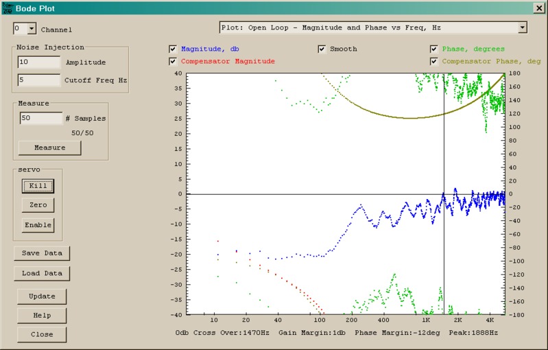
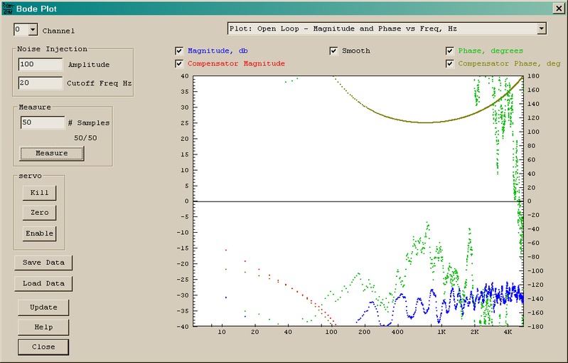
09-step-I0.000001.txt .. step test, I gain = 0.000001As you can see, I=0.1 was resonating like hell and the biggest I value that didn't make things much worse than open loop, was I = 1E-6 However, I couldn't get a bode plot with I as small as 1E-6 and had to raise it up to 1E-3 in order to be able to see something. 10-newsettings.png .... step response with I gain = 1E-3
11-bode100-20-50.png .. bode plot with I = 1E-3
12-bode10-5-50.png .... another bode plot with I = 1E-3I didn't understand what the "cutoff frequency" parameter is supposed to do. In the attached pictures, the plot always starts at 10 Hz regardless the cutoff is set to 5 Hz in one case and to 20 Hz in the other case. Is the cutoff meant to be a upper limit or a lower limit? The documentation says it mustn't be too small or too high but I didn't understand when it's too small and when it's too big so I don't know how to act on it... but I saw that certain combinations of amplitude and cutoff, have the effect that the plot shows nothing... Thank you again EC ---In DynoMotion@yahoogroups.com, <tk@...> wrote : Hi Eric.
I assume you meant to say a "Move" command on the Step Response Screen?
What you are trying to do is a bit unusual. You are closing a position loop around another position loop using the same encoder. It doesn't really make much sense to do this. The drive should be able to close the loop just as well as KFLOP could - unless the drive is missing some capability like filtering or doesn't have as good of tools to find the correct parameters in the first place.
Also closing one loop around another to try to improve it is complex. An analogy might be something like this: Imagine a drunk person is driving a car weaving down the road. A simple approach would be to put them to sleep and let you drive. But that's not what you are doing. Rather what you doing is more like leaving them drive, but then watching how they drive down the road and adjusting where they see the lines on the road, to attempt to keep them more centered on the
road. You need to compensate for both the characteristics of the car as well as the characteristics of the drunk driver. If they are slow to react to commands it makes things very difficult if not impossible.
But one thing that usually does work is to correct slow gradual drifts. If the drunk driver persistently drives on the shoulder of the road, then you could gradually shift the lines on the road over a
few feet to improve things. But quickly shifting lines would be likely to cause the drunk driver to over correct and begin weaving.
The I gain factor can be used for this. It observes and accumulates how much and for how long the error has been on one side and shifts the target accordingly. You probably have just added too much I gain. I gain is usually a small number like 0.0001. There will
always be some number where the system is still stable although it may not help much in correcting errors quickly. If the drive has effective Integrator gain then the average error should already be zero.
So I think your focus should first be to determine how well your drive is performing on its own (with KFLOP PID parameters zero). You say it "has quite good response" so I'm not
really sure what you are doing this for. Post some plots so we can see what you mean. What are the following errors and at what velocities and accelerations? You should also tell us what type of machine this is, what the resolution is, and what your expectations are.
Then you might perform a Bode Plot (again with KFLOP PID parameters zero). A Bode Plot is essentially testing the system by giving it a test track that curves
back and forth at different frequencies. One could characterize the performance by testing on hundreds of different race tracks each with a different frequency of curves, but that would take a long time. Instead we use a test track with all manner of different random curves. The math then basically determines how the system did where the frequency was this and that. It then analyzes the data to see how well it follows each frequency and plots it on a graph. Generally systems follow slow gradual curves very accurately. As the curves become tighter and faster the errors will become larger. Basically where a Bode plot shows high gain this indicates it did very well. Where the gain is very small (less than 1 which is the same as less than 0db) the system hardly followed the path at all. The first frequency where the gain drops to 0db is what is commonly referred to as the bandwidth of the system. This is
where about half of the error is being corrected - not very good, but still much better than nothing. So bandwidth is a good figure of merit to describe how dynamically responsive a system is.
As pointed out in the help files that in order to get a Bode plot that is actually meaningful it must be stimulated by a reasonable amount. The stimulation amplitude is basically how much the curves in the road go back and forth. Theoretically a perfect system with infinite available power and
infinite resolution would have the same dynamic response regardless of the amplitude of the curves and the Bode plot would come out the same. But in the real world things are not like that. Imagine curves too large where the car steering wheel hits the stops left and right (amplifier saturation) then the result will be incorrect and meaningless. If the curves are too tiny then it will be difficult to even measure if the car is following them (encoder quantization error). Normally KFLOP's stimulation output is something like motor current so it is easy to see how hard we are driving the system. But unfortunately in your case the output is position and the motor current is in the drive which we can't see. This makes it extra hard to see if we are stimulating the system in a reasonable manner.
Let me know how much of this makes sense. Regards TK
|
|
|
@@attachment@@
|
| Group: DynoMotion |
Message: 10450 |
From: ericncn |
Date: 11/2/2014 |
| Subject: Re: do my servos behave normally? [OT] |
Hi Tom,
first of all I thank you for your time.
I've just sent another message with the results of the step response, bode plots etc. Here I'm going to answer your other questions. I believe there has been a little misunderstanding, I'll try to clarify.
> I assume you meant to say a "Move" command on the Step Response Screen?
I performed both "Move" and "Step" tests. Just sent the results.
> What you are trying to do is a bit unusual. You are closing a position
> loop around another position loop using the same encoder. It doesn't
> really make much sense to do this.
In fact, I agree it doesn't make sense, I didn't want to do that.
But that was the only way to get a bode plot (see the other message) so I had to try.
My servo drives would also work in torque mode or velocity mode, and could accept commands in step/dir, quadrature or PWM formats (page 23 of the drive manual, link below) but I found no way to tell Kflop to use that modes. I tried all Kflop modes but the only modes that cause the motor to rotate, are "stepper" and "CL step".
> You probably have just added too much I gain. I
> gain is usually a small number like 0.0001
The default value suggested by Kmotion was 0.1. Now I've tried all values ranging from 1E-1 to 1E-6, see the other email for results.
> So I think your focus should first be to determine how well your drive
> is performing on its own (with KFLOP PID parameters zero).
Sure, I agree, but as pointed out previously, I can't get a bode plot if PID is set to 0,0,0 and the smallest 'I' that's big enough to get a bode plot, is already causing significant overshoot.
I believe this is because the gains in the servo drive were already raised to the limit (I spent hours on it), the smallest gain I add via the Kflop, makes it overshoot and/or resonate.
What about if I lower the gains in the servo drive (so it would follow the commands a bit slowly but would become stable) then add the missing part of the gain in the Kflop loop ?
> You say it
> "has quite good response" so I'm not really sure what you are doing this
> for. Post some plots so we can see what you mean.
I've sent the plots in the other message. I consider the step response good but as you can see the bode plot is dramatic. However that bode plot is done with 'I' = 1E-3 and that's not PID=0,0,0 like you asked (and like when the machine is normally working...)
> You should
> also tell us what type of machine this is, what the resolution is, and
> what your expectations are.
It's a 3-axis milling machine, the motors direct driving the axis, and a resolution of 2,500 lines per revolution (10,000 counts after quadrature).
These are the motor drives:
http://granitedevices.fi/assets/files/vsd-e_160_manual.pdf
see pages 23-25 for the control modes and the internal control loops.
My expectations:
in a previous message I reported I can turn an axis out of position by hand a little bit, before it reacts and returns to the intended position, and asked if this was normal.
You explained me about overshooting and windup, implying this wasn't necessary to happen so, my expectations would be to fix it.
Would like the motor to be stiffer, i.e. to react much quicker when I try to turn it and not overshoot when I release it.
> Then you might perform a Bode Plot (again with KFLOP PID parameters
> zero). A Bode Plot is essentially [...]
I thank you for summing up the bode plots in a few words. Now it's clear, I got it, and also the help documentation starts making sense. For some reasons, I couldn't get it from the documentation alone.
> Let me know how much of this makes sense.
All you wrote makes perfectly sense.
Thank you again for your time and patience
EC |
|
| Group: DynoMotion |
Message: 10452 |
From: Tom Kerekes |
Date: 11/2/2014 |
| Subject: Re: do my servos behave normally? [OT] |
Hi EC,
Thank you for answering the questions, providing detailed info, and your patience.
Regarding "Move" and "Step" tests: I'm surprised "Step" even works. It normally doesn't make sense with Step/Dir drives to instantly jump some place. KFLOP will react at Max Pulse Rate (2.5MHz) which is normally just lost by the drive. I believe you said you were using quadrature mode. So that is a testament to quadrature mode and the Granite Devices Drives that they count at that high rate. But restrict to performing "Move" tests in the future please.
Looks like the Granite Drive does support an anti-phase mode of PWM input (50% duty cycle is zero velocity or torque). But I can't find where it specifies the valid frequency range. Since you are currently wired and the drive is configured as Step/Dir mode none of the other KFLOP output modes will work. CL Step/Dir is still outputting Step/Dir pulses. To use PWM mode would take some work - wiring, configuration changes, a C Program to control the PWM etc...
I think the thing to remain focused on is testing the performance and tuning of the Granite Devices Drive. Remain in CL Step/Dir mode but with PID zero. I'm not completely sure but I think the Bode plot is so low simply because the performance is so low. But what contradicts this is when you do Move plots the performance looks pretty good. What do you think the performance is? I remember you stated that the performance was poor. Very sloppy and you could move the motors away from the
target. But then I thought you re-tuned the drive and it was better?
It could be that you are using Feed Forward in the drive to get the reasonable response. If you have FF in the drive turned on try turning it off. FF is like driving with your eyes closed (open loop). If you know a curve is coming up you might close your eyes and turn the steering wheel the expected amount for the curve and make the curve pretty well. But if anything varies like slippery road (friction
changes), wind gusts (load disturbances), etc you will likely run off the road. FF can sometimes be helpful as otherwise we are basically ignoring the up coming curve completely until we start running off the road before we begin to start making the turn. But servo feedback should be optimized first because it works under varying conditions where FF does not. Your Step/Move plots sort of lead me to think that the drive FF is mainly used. Notice it has great/quick response to the initial Step/Move but then misses the target by a small amount. It then takes a very long time to correct the error (~1/2 second).
Regarding the Bode plot stimulation frequency cutoff: again the idea is that to get a good Bode plot we must properly stimulate the system otherwise we just get garbage. It is sort of like shaking a box to see what is inside. Too hard is no good and too soft is no good. But there is also a frequency component to the stimulus. We want to do stimulus at the frequencies of interest. Normal white noise contains all frequencies equally. But most systems have no response to the higher frequencies which results in lots of stimulus in areas of no interest (and other bad things). So by lowering the cutoff frequency the higher stimulus frequencies are reduced in amplitude. The cutoff is not sharp. It is just a gradual roll off that begins at that frequency
and attenuates more and more at higher and higher frequencies. I think your system is low performance so we should set the cutoff frequency low so as to get more information at lower frequencies (ie 1~5Hz).
You should always observe the Time domain Plot on the Bode Plot screen before attempting to measure a Bode Plot. I don't think you included any of those. This allows you to see the Stimulus applied in the Time Domain (like a scope would). That is the Blue plot. The Red
plot is the system response. It should somewhat follow the Blue Plot at least where the Blue plot changes more slowly.
Regards TK
From: "ericnc@... [DynoMotion]" <DynoMotion@yahoogroups.com>
To: DynoMotion@yahoogroups.com
Sent: Sunday, November 2, 2014 10:16 AM
Subject: Re: [DynoMotion] Re: do my servos behave normally?
[OT]
Hi Tom,
first of all I thank you for your time.
I've just sent another message with the results of the step response, bode plots etc. Here I'm going to answer your other questions. I believe there has been a little misunderstanding, I'll try to clarify.
> I assume you meant to say a "Move" command on the Step Response Screen?
I performed both "Move" and "Step" tests. Just sent the results.
> What you are trying to do is a bit unusual. You are closing a position
> loop around another position loop using the same encoder. It doesn't
> really make much sense to do this.
In fact, I agree it doesn't make sense, I didn't want to do that.
But that was the only way to get a bode plot (see the other message) so I had to try.
My servo drives would also work in torque mode or velocity mode, and could accept commands in step/dir, quadrature or PWM formats (page 23 of the drive manual, link below) but I found no way to tell Kflop to use that modes. I tried all Kflop modes but the only modes that cause the motor to rotate, are "stepper" and "CL step".
> You probably have just added too much I gain. I
> gain is usually a small number like 0.0001
The default value suggested by Kmotion was 0.1. Now I've tried all values ranging from 1E-1 to 1E-6, see the other email for results.
> So I think your focus should first be to determine how well your drive
> is performing on its own (with KFLOP PID parameters zero).
Sure, I agree, but as pointed out previously, I can't get a bode plot if PID is set to 0,0,0 and the smallest 'I' that's big enough to get a bode plot, is already causing significant overshoot.
I believe this is because the gains in the servo drive were already raised to the limit (I spent hours on it), the smallest gain I add via the Kflop, makes it overshoot and/or resonate.
What about if I lower the gains in the servo drive (so it would follow the commands a bit slowly but would become stable) then add the missing part of the gain in the Kflop loop ?
> You say it
> "has quite good response" so I'm not really sure what you are doing this
> for. Post some plots so we can see what you mean.
I've sent the plots in the other message. I consider the step response good but as you can see the bode plot is dramatic. However that bode plot is done with 'I' = 1E-3 and that's not PID=0,0,0 like you asked (and like when the machine is normally working...)
> You should
> also tell us what type of machine this is, what the resolution is, and
> what your expectations are.
It's a 3-axis milling machine, the motors direct driving the axis, and a resolution of 2,500 lines per revolution (10,000 counts after quadrature).
These are the motor drives:
http://granitedevices.fi/assets/files/vsd-e_160_manual.pdf
see pages 23-25 for the control modes and the internal control loops.
My expectations:
in a previous message I reported I can turn an axis out of position by hand a little bit, before it reacts and returns to the intended position, and asked if this was normal.
You explained me about overshooting and windup, implying this wasn't necessary to happen so, my expectations would be to fix it.
Would like the motor to be stiffer, i.e. to react much quicker when I try to turn it and not overshoot when I release it.
> Then you might perform a Bode Plot (again with KFLOP PID parameters
> zero). A Bode Plot is essentially [...]
I thank you for summing up the bode plots in a few words. Now it's clear, I got it, and also the help documentation starts making sense. For some reasons, I couldn't get it from the documentation alone.
> Let me know how much of this makes sense.
All you wrote makes perfectly sense.
Thank you again for your time and patience
EC
|
|
| Group: DynoMotion |
Message: 10454 |
From: ericncn |
Date: 11/2/2014 |
| Subject: Re: do my servos behave normally? [OT] |
Hi Tom, thank you for helping. Here are the answers: - Yes I'm using quadrature mode (output channel 24: LVTTL-Quadrature). - OK I'll only do "Move" tests in the future. - The drive input PWM frequency range is 3 to 100 Kz with typical values 5 to 30 KHz (it's on page 4 here: http://granitedevices.fi/assets/files/vsd-e_160_manual.pdf ). I am willing to try torque mode but OK, let's complete testing first. - yes I think the performance is poor. Milling is a pain, I must keep low feed and low spindle speed or it vibrates too much. - yes very sloppy and I could move the motors away from the target, but after a little time the motors react (increase torque) and return to target. The motor torque isn't insufficient, it's that they are slow to react. - yes I re-tuned the motor (singular, I'm doing all the experimentation on the X axe only) according your suggestions and it has improved significantly. Let's say it's twice as rigid as before, and reaction time is shorter, but it isn't rock solid. - yes Feed Forward and other "forwards" are used in the drive. That was part of my tuning effort. I'll set them back to zero. Also there's an "input filter" and it says to turn it off if the encoder position is managed externally. I can disable that too. Accessing the drive parameters requires me to do a little rewiring each time. While I'm at it, are there other things I could do? For example there's an "anti-dither" bandwidth I used to reduce "whistling" when using high gains, should I turn it off and reduce the gains? - thank you for the additional explanations about the bode plots. OK I'll keep the cutoff frequencies in the range 1-5 Hz. I had already seen that using 20 Hz, often produces a blank plot. - I didn't post either data files or screen captures of the time domain plot on the bode plot screen, because they looked meaningless. Nothing to do with the examples in the documentation. The red line totally unrelated to the blue line. In most case the red line is flat, it just ignores the stimulus. Other times it just goes up and down in a square wave similar to a PWM (I mean, moving between two values, always the same) - so, do I just turn off feed forward, velocity forward, etc. in the drive and redo the bode plot with PID = 0 ? Please remember that if PID is zero, bode plot doesn't plot anything. Thank you, EC ---In DynoMotion@yahoogroups.com, <tk@...> wrote : Hi EC,
Thank you for answering the questions, providing detailed info, and your patience.
Regarding "Move" and "Step" tests: I'm surprised "Step" even works. It normally doesn't make sense with Step/Dir drives to instantly jump some place. KFLOP will react at Max Pulse Rate (2.5MHz) which is normally just lost by the drive. I believe you said you were using quadrature mode. So that is a testament to quadrature mode and the Granite Devices Drives that they count at that high rate. But restrict to performing "Move" tests in the future please.
Looks like the Granite Drive does support an anti-phase mode of PWM input (50% duty cycle is zero velocity or torque). But I can't find where it specifies the valid frequency range. Since you are currently wired and the drive is configured as Step/Dir mode none of the other KFLOP output modes will work. CL Step/Dir is still outputting Step/Dir pulses. To use PWM mode would take some work - wiring, configuration changes, a C Program to control the PWM etc...
I think the thing to remain focused on is testing the performance and tuning of the Granite Devices Drive. Remain in CL Step/Dir mode but with PID zero. I'm not completely sure but I think the Bode plot is so low simply because the performance is so low. But what contradicts this is when you do Move plots the performance looks pretty good. What do you think the performance is? I remember you stated that the performance was poor. Very sloppy and you could move the motors away from the
target. But then I thought you re-tuned the drive and it was better?
It could be that you are using Feed Forward in the drive to get the reasonable response. If you have FF in the drive turned on try turning it off. FF is like driving with your eyes closed (open loop). If you know a curve is coming up you might close your eyes and turn the steering wheel the expected amount for the curve and make the curve pretty well. But if anything varies like slippery road (friction
changes), wind gusts (load disturbances), etc you will likely run off the road. FF can sometimes be helpful as otherwise we are basically ignoring the up coming curve completely until we start running off the road before we begin to start making the turn. But servo feedback should be optimized first because it works under varying conditions where FF does not. Your Step/Move plots sort of lead me to think that the drive FF is mainly used. Notice it has great/quick response to the initial Step/Move but then misses the target by a small amount. It then takes a very long time to correct the error (~1/2 second).
Regarding the Bode plot stimulation frequency cutoff: again the idea is that to get a good Bode plot we must properly stimulate the system otherwise we just get garbage. It is sort of like shaking a box to see what is inside. Too hard is no good and too soft is no good. But there is also a frequency component to the stimulus. We want to do stimulus at the frequencies of interest. Normal white noise contains all frequencies equally. But most systems have no response to the higher frequencies which results in lots of stimulus in areas of no interest (and other bad things). So by lowering the cutoff frequency the higher stimulus frequencies are reduced in amplitude. The cutoff is not sharp. It is just a gradual roll off that begins at that frequency
and attenuates more and more at higher and higher frequencies. I think your system is low performance so we should set the cutoff frequency low so as to get more information at lower frequencies (ie 1~5Hz).
You should always observe the Time domain Plot on the Bode Plot screen before attempting to measure a Bode Plot. I don't think you included any of those. This allows you to see the Stimulus applied in the Time Domain (like a scope would). That is the Blue plot. The Red
plot is the system response. It should somewhat follow the Blue Plot at least where the Blue plot changes more slowly.
Regards TK
|
|
| Group: DynoMotion |
Message: 10457 |
From: Tom Kerekes |
Date: 11/2/2014 |
| Subject: Re: do my servos behave normally? [OT] |
Hi EC,
I realize now you are correct. For CL Step/Dir the Bode Plot is not included in the FF path to the output (only through the PID). Please try the new Test Version 4.33i that we just posted.
I don't have a CL Step/Dir handy to test. So please let me know if you now get something reasonable for a Bode Plot.
I can't think of anything else to change in the Drive.
Regards TK
| Group: DynoMotion |
Message: 10466 |
From: ericncn |
Date: 11/3/2014 |
| Subject: Re: do my servos behave normally? [OT] |
Thank you! Will try it as soon as possible and let you know how it works. In the while, I had found a combination of PID parameters (within KMotion) and integrator max limit that reproduced the behavior of PID=0,0,0, if not slightly better. But there were no significant improvements in the bode plots. Wil let you know ASAP! Thank you EC ---In DynoMotion@yahoogroups.com, <tk@...> wrote : Hi EC,
I realize now you are correct. For CL Step/Dir the Bode Plot is not included in the FF path to the output (only through the PID). Please try the new Test Version 4.33i that we just posted.
I don't have a CL Step/Dir handy to test. So please let me know if you now get something reasonable for a Bode Plot.
I can't think of anything else to change in the Drive.
Regards TK |
|
| Group: DynoMotion |
Message: 10470 |
From: ericncn |
Date: 11/3/2014 |
| Subject: Re: do my servos behave normally? [OT] |
Hi Tom, I tried 4.33i shortly and it seems me that yes, now the bode plot works even in CL step mode with PID zero, and even in plain stepper mode. However ther was no improvement in the bode plots. After that I entered the servo drive setup and turned off the input noise filter (I realized that you want to measure noise, so...) and also the velocity and aceleration feed forwards. This made a difference. Now I can see (hear) the effect of changing the amplitude and freq.cutoff parameters. The higher the amplitude, or the higher the cutoff frequency, and the harder I can hear the motor work. And, I can now get the bode plots but the function is all below zero dB. Today I was in the hurry and could not produce screenshots and data files to post. Will do as soon as possible, together with more experiments... Thank you EC ---In DynoMotion@yahoogroups.com, <tk@...> wrote : Hi EC,
I realize now you are correct. For CL Step/Dir the Bode Plot is not included in the FF path to the output (only through the PID). Please try the new Test Version 4.33i that we just posted.
I don't have a CL Step/Dir handy to test. So please let me know if you now get something reasonable for a Bode Plot.
I can't think of anything else to change in the Drive.
Regards TK
| Group: DynoMotion |
Message: 10473 |
From: ericncn |
Date: 11/5/2014 |
| Subject: Re: do my servos behave normally? [OT] |
Hi Tom, here you find attached some screenshots and a zip file containing the corresponding data files. Since previous time and following your advice, I've turned off the velocity FF and the acceleration FF in the servo drive. (I also turned off the input noise filter and sligtly de-tuned the PIV parameters so it didn't whistle all the time while holding position.) Remember my sysem has currently a huge load inertia ratio (should be somewhere between 80 and 100); also I always said it's "direct drive" meaning there is no reduction ratio, but there's a coupler between the motor and the lead screw axis. I read somewhere that the higher the load inertia ratio, the stiffer must be the coupling. Maybe the problem is the coupler? Thank you EC ---In DynoMotion@yahoogroups.com, <tk@...> wrote : Hi EC,
I realize now you are correct. For CL Step/Dir the Bode Plot is not included in the FF path to the output (only through the PID). Please try the new Test Version 4.33i that we just posted.
I don't have a CL Step/Dir handy to test. So please let me know if you now get something reasonable for a Bode Plot.
I can't think of anything else to change in the Drive.
Regards TK
|
|
|
@@attachment@@
|
| Group: DynoMotion |
Message: 10474 |
From: Tom Kerekes |
Date: 11/6/2014 |
| Subject: Re: do my servos behave normally? [OT] [10 Attachments] |
Hi EC,
It still isn't making sense to me. I think it premature to try to make Bode plots. The Move response has a large lag for some reason. Approximately 300-600 counts.
We probably need to get the drive working better first. Unfortunately it is sort of a chicken and egg problem. The tuning needs to be pretty good in order to get a good Bode plot to figure out what is wrong with the tuning.
You should also plot the Time domain of the Bode Stimulus to see what is going on.
It probably isn't a good idea to set the number of Bode Samples so high as 50. It becomes misleading. By averaging 50 random garbage plots the result can look reasonable (smooth) but is really meaningless.
Regards TK
| Group: DynoMotion |
Message: 10475 |
From: ericncn |
Date: 11/6/2014 |
| Subject: Re: do my servos behave normally? [OT] [10 Attachments] |
Hi Tom, I confirm that while doing the 50 samples, each plot was "jumping" from previous one. However I attached the data files so you could have all the information. Anyway, in the while I couldn't resist to try and disconnect the load from the motor. I only left half of the coupler on the motor shaft. Here's what I did in the past few hours: 1) it was vibrating violently. 2) I re-tuned it (at drive level) by lowering the gains by about ten times until it became stable 3) I made a bode plot (first attachment). It finally makes some sense. I guess this is the upper limit of the system performance, and it also demonstrates the problem is the load (or the way the load is coupled) 4) I tried enabling the CL loop mode and added some small gains to the PID at KMotion level 5) I re-made the bode plot (second attachements) which shows some improvement (actually I run it a few times and it always gave same result) Does this help undertanding what's happening? I can send the corresponding data files; I also have a "move" plot and data file, made after disconnecting the load and with PID not yet enabled Thank you EC ---In DynoMotion@yahoogroups.com, <tk@...> wrote : Hi EC,
It still isn't making sense to me. I think it premature to try to make Bode plots. The Move response has a large lag for some reason. Approximately 300-600 counts.
We probably need to get the drive working better first. Unfortunately it is sort of a chicken and egg problem. The tuning needs to be pretty good in order to get a good Bode plot to figure out what is wrong with the tuning.
You should also plot the Time domain of the Bode Stimulus to see what is going on.
It probably isn't a good idea to set the number of Bode Samples so high as 50. It becomes misleading. By averaging 50 random garbage plots the result can look reasonable (smooth) but is really meaningless.
Regards TK
|
|
|
@@attachment@@
|
| Group: DynoMotion |
Message: 10476 |
From: Dan |
Date: 11/6/2014 |
| Subject: Re: do my servos behave normally? [OT] [2 Attachments] |
EC,
What kind of machine are these motors on? Is this a CNC mill? is it a
retorfit or new build? I would like to know more about the application. I am
wondering if the motors are the right side. My next question for you is where
are you located, maybe I can call you and walk through how I tuned mine (not
that I know best, but my mill is working).
As Tom was getting at before the Bode plot is not very useful at this stage
of tuning. I would go farther and say don’t use it yet, you need to get your
drives tuned to the motors and system they are connected to first. On my mill I
have only used the Bode plot for one thing, that was to determine the response
of the system so I could set the response frequency in my servo drives. But that
was for a closed loop system with analog drives. I maybe wrong but the response
of the system may change depending on drive mode and load.
Dan
Sent: Thursday, November 06, 2014 5:16 PM
Subject: Re: [DynoMotion] Re: do my servos behave normally? [OT] [2
Attachments]
Hi Tom,
I confirm that while doing the 50 samples, each plot was
"jumping" from previous one. However I attached the data files so you could have
all the information.
Anyway, in the while I couldn't resist to try and
disconnect the load from the motor. I only left half of the coupler on the motor
shaft. Here's what I did in the past few hours:
1) it was vibrating
violently.
2) I re-tuned it (at drive level) by lowering the gains by
about ten times until it became stable
3) I made a bode plot (first
attachment). It finally makes some sense. I guess this is the upper limit of the
system performance, and it also demonstrates the problem is the load (or the way
the load is coupled)
4) I tried enabling the CL loop mode and added some
small gains to the PID at KMotion level
5) I re-made the bode plot
(second attachements) which shows some improvement
(actually I run it a few
times and it always gave same result)
Does this help undertanding what's
happening?
I can send the corresponding data files; I also have a "move" plot
and data file, made after disconnecting the load and with PID not yet enabled
Thank you
EC
---In DynoMotion@yahoogroups.com, <tk@...> wrote
:
Hi EC,
It
still isn't making sense to me. I think it premature to try to make Bode
plots. The Move response has a large lag for some reason.
Approximately 300-600 counts.
We
probably need to get the drive working better first. Unfortunately it is
sort of a chicken and egg problem. The tuning needs to be pretty good in
order to get a good Bode plot to figure out what is wrong with the
tuning.
You
should also plot the Time domain of the Bode Stimulus to see what is going
on.
It
probably isn't a good idea to set the number of Bode Samples so high as
50. It becomes misleading. By averaging 50 random garbage plots the
result can look reasonable (smooth) but is really meaningless.
Regards
TK
|
|
| Group: DynoMotion |
Message: 10477 |
From: Steve Klemp |
Date: 11/7/2014 |
| Subject: Re: do my servos behave normally? [OT] |
Hi Dan, What kind of mill did you retrofit? What motors (stepper/servos) did you use? I have completed my last project and I am getting ready for a new one. I just bought a Series 1 Bridgeport to retrofit and I am going to order another Kflop, and kanalog from Tom. I am not real sure what size / type motors to use. Was just wondering what others are using. I am located in Texas
| Group: DynoMotion |
Message: 10481 |
From: ericncn |
Date: 11/9/2014 |
| Subject: Re: do my servos behave normally? [OT] [2 Attachments] |
Hello Dan, this is a 3-axis benchtop mill and it's more a new build than a retrofit. It weights some 400-500 lbs (don't know exactly). Motors torque is about 1.3/3.9 Nm (continuous/peak), encoders have 2,500 lines (10,000 counts). I know they're a bit undersized and I initially meant to use a reduction ratio. But in order to test KFlop wiring and also for simplicity of first installation, I "temporarily" hooked the motors direct drive (1:1) with a cheap coupler that I now know it's not enough rigid for the task. All this was meant as a temporary setup (hence as cheap as possible) just to have the machine somehow up and running, and to use it for machining the more complex adapter plates for the final setup with pulleys and belts. But the machine was vibrating so badly doing any milling work that wasn't ridiculously light, I concluded the mechanical structure was too flexible. At this point Tom suggested that it could be possible that it wasn't the mechanical structure fault, that a reduction ratio wouldn't necessarily help, and that the inertia load ratio isn't very related to vibrations. And that the KFlop has tools (dumping data, and bode plots) for analyzing and understanding what's happening. Hence what I'm doing now is following Tom's directions in order to understand what to do next. I agree the motors could/should/must be tuned better and I made some progresses last night (when motor is disconnected from load, the bode plot is a useful tool for measuring how the PID parameters affect performance). It's very kind of you to be willing to call me and walk me through the tuning process, I'm going to write you privately about this. Thank you, EC ---In DynoMotion@yahoogroups.com, <engnerdan@...> wrote : EC, What kind of machine are these motors on? Is this a CNC mill? is it a
retorfit or new build? I would like to know more about the application. I am
wondering if the motors are the right side. My next question for you is where
are you located, maybe I can call you and walk through how I tuned mine (not
that I know best, but my mill is working). As Tom was getting at before the Bode plot is not very useful at this stage
of tuning. I would go farther and say don’t use it yet, you need to get your
drives tuned to the motors and system they are connected to first. On my mill I
have only used the Bode plot for one thing, that was to determine the response
of the system so I could set the response frequency in my servo drives. But that
was for a closed loop system with analog drives. I maybe wrong but the response
of the system may change depending on drive mode and load. Dan
|
|
| Group: DynoMotion |
Message: 10482 |
From: Dan |
Date: 11/9/2014 |
| Subject: Re: do my servos behave normally? [OT] |
EC,
Thanks for the info, my concern I had in the back of my head was that maybe
you do not have enough inertia in your motors for the connected load. A few
years ago I had a machine at work that the servo vendor mis-calculated the motor
size for the load and task we were doing. They gave spec’ed a 150W low inertia
motor and I ended up using a 750W medium inertia motor. Before I knew the motor
size was wrong I spent 2 weeks trying to tune the motor and going back and forth
with the factory. No matter what I did I could not get the motor to no over
shoot and resonate.
I am not saying that is what you have going on, as I don’t have enough
information. But I do know a gear or belt drive to change the ratio would help.
If I remember correctly, while the drive ratio changes linearly the inertia the
motor has to counteract changes at the square of the ratio or something along
those lines.
My mill is about 1200lbs, I started with a Novakon Torus Pro that was
stripped of all motors and controls and then I fit servos of my choice and a
KFLOP and KANALOG to it. I am using Teco servos with a 750 Watt medium inertia
motors on the X and Y, and a 1000W Med-High inertia motor on the Z axis. My
machine seems to be working very well and I think I am under 200 encoder counts
(10,000 per rev) error, with most of the error at the initial acceleration from
a stop and the deceleration to a stop. It would not have been a bad thing for me
to have more inertia in the X and Y but that was not offered.
Dan
Sent: Sunday, November 09, 2014 6:33 AM
Subject: Re: [DynoMotion] Re: do my servos behave normally?
[OT]
Hello Dan,
this is a 3-axis benchtop mill and it's more a new build
than a retrofit. It weights some 400-500 lbs (don't know exactly). Motors torque
is about 1.3/3.9 Nm (continuous/peak), encoders have 2,500 lines (10,000
counts). I know they're a bit undersized and I initially meant to use a
reduction ratio.
But in order to test KFlop wiring and also for simplicity of
first installation, I "temporarily" hooked the motors direct drive (1:1) with a
cheap coupler that I now know it's not enough rigid for the task.
All
this was meant as a temporary setup (hence as cheap as possible) just to have
the machine somehow up and running, and to use it for machining the more complex
adapter plates for the final setup with pulleys and belts. But the machine was
vibrating so badly doing any milling work that wasn't ridiculously light, I
concluded the mechanical structure was too flexible.
At this point Tom
suggested that it could be possible that it wasn't the mechanical structure
fault, that a reduction ratio wouldn't necessarily help, and that the inertia
load ratio isn't very related to vibrations.
And that the KFlop has tools
(dumping data, and bode plots) for analyzing and understanding what's
happening.
Hence what I'm doing now is following Tom's directions in
order to understand what to do next.
I agree the motors could/should/must
be tuned better and I made some progresses last night (when motor is
disconnected from load, the bode plot is a useful tool for measuring how the PID
parameters affect performance). It's very kind of you to be willing to call me
and walk me through the tuning process, I'm going to write you privately about
this.
Thank you,
EC
---In DynoMotion@yahoogroups.com,
<engnerdan@...> wrote :
EC,
What kind of machine are these motors on? Is this a CNC mill? is it a
retorfit or new build? I would like to know more about the application. I am
wondering if the motors are the right side. My next question for you is where
are you located, maybe I can call you and walk through how I tuned mine (not
that I know best, but my mill is working).
As Tom was getting at before the Bode plot is not very useful at this stage
of tuning. I would go farther and say don’t use it yet, you need to get your
drives tuned to the motors and system they are connected to first. On my mill I
have only used the Bode plot for one thing, that was to determine the response
of the system so I could set the response frequency in my servo drives. But that
was for a closed loop system with analog drives. I maybe wrong but the response
of the system may change depending on drive mode and load.
Dan
|
|
| Group: DynoMotion |
Message: 10483 |
From: ericncn |
Date: 11/10/2014 |
| Subject: Re: do my servos behave normally? [OT] |
Dan,
in fact it looks like my case is similar to yours.
Too small motors for the machine, and trying to tune the system as is leads to overshooting and vibrations.
Load inertia ratio is huge (a rough estimation using Kollmorgen free software shows it's about 100:1 or something like that) and I believe the coupler, not enough rigid for this task, acts as a damper, or a filter, so that while the motor oscillates like crazy the mill table stays substantially still.
So what I tried to do is to tune one motor (the X asis) with the load disconnected. This way I could make it significantly stiffer and vibrations-free at the same time. And of course stiffness doesn't change when I reconnect it to the load.
I have collected some data that I will post here as soon as I have a chance to download it from the machine.
Regards,
EC
---In DynoMotion@yahoogroups.com, <engnerdan@...> wrote :
EC,
Thanks for the info, my concern I had in the back of my head was that maybe you do not have enough inertia in your motors for the connected load. A few years ago I had a machine at work that the servo vendor mis-calculated the motor size for the load and task we were doing. They gave spec’ed a 150W low inertia motor and I ended up using a 750W medium inertia motor. Before I knew the motor size was wrong I spent 2 weeks trying to tune the motor and going back and forth with the factory. No matter what I did I could not get the motor to no over shoot and resonate.
I am not saying that is what you have going on, as I don’t have enough information. But I do know a gear or belt drive to change the ratio would help. If I remember correctly, while the drive ratio changes linearly the inertia the motor has to counteract changes at the square of the ratio or something along those lines.
My mill is about 1200lbs, I started with a Novakon Torus Pro that was stripped of all motors and controls and then I fit servos of my choice and a KFLOP and KANALOG to it. I am using Teco servos with a 750 Watt medium inertia motors on the X and Y, and a 1000W Med-High inertia motor on the Z axis. My machine seems to be working very well and I think I am under 200 encoder counts (10,000 per rev) error, with most of the error at the initial acceleration from a stop and the deceleration to a stop. It would not have been a bad thing for me to have more inertia in the X and Y but that was not offered.
Dan |
|
| Group: DynoMotion |
Message: 10507 |
From: ericncn |
Date: 11/12/2014 |
| Subject: Re: do my servos behave normally? [OT] |
|
In previous message I sent results of tests performed after disconnecting one motor from load and re-tuning it without load, and after enabling CL mode in Kflop, still with PID parameters zeroed.
Here follows what I've done next:
added some small gains:
0101-move-noload.png
0103-bode-noload-time.png
0104-bode-noload-freq.png
(phase gain improved significantly)
Then I reconnected the motor to the load:
0201-move.png
0202-bode-time.png
0203-bode-freq.png
and things went - obviously - bad again, except that if I try to turn the motor by hand, it now feels significantly more rigid than before.
I later did some more tuning (not documented in previous pictures) and tried to measure the following error by the sample program PrintFollowErr.c and it looks like I can't move it by hand more than 5-10 counts before it takes over and goes back to zero.
If I do a fast jog instead, the following error is constantly over 300 counts.
Is this nornal?
EC
|
|
|
@@attachment@@
|
| Group: DynoMotion |
Message: 10508 |
From: Tom Kerekes |
Date: 11/13/2014 |
| Subject: Re: do my servos behave normally? [OT] [6 Attachments] |
Hi EC,
As you can see from the Bode Plot Time Domain Plots the encoder is hardly moving 1 encoder count. In those cases the Bode Plot will be meaningless.
It isn't normal to have a 300 count following error while jogging at constant velocity. You might make an equivalent move as the Jog on the Step Response Screen and observe the response as a plot. Possibly the Drive is doing some sort of filtering or smoothing which generates a lag?
Regards TK
| Group: DynoMotion |
Message: 10601 |
From: ericncn |
Date: 11/30/2014 |
| Subject: Re: do my servos behave normally? [OT] [6 Attachments] |
Hi TK, I had previously disabled the input filter in the drive. The lag during constant moves depends on speed i.e. jogging at 0.25 inches/sec the lag is about 25-30 counts while jogging at 1 inch/second it becomes about 315 counts. If I make an equivalent move in the Step Response Screen i get same result: the output plot is same as the input plot, but shifted to the right The system has friction (or the motor is undersized, which is the same). By trial and error I've determined the minimum torque needed for moving at slow speed without getting stuck and it's about 23% of the rated torque (minimum current that makes the motor move the axis is 800 mA while rated current is 3.5 A). I have no other servo systems to compare but I guess that's "a lot". Actually the lag at 1 inch/second would be about 570 counts, but I managed to trim it down to about 315 counts by adding feed forwards in Kmotion (I left the feed forwards disabled in the motor drive like you asked). Thank you EC ---In DynoMotion@yahoogroups.com, <tk@...> wrote Hi EC,
As you can see from the Bode Plot Time Domain Plots the encoder is hardly moving 1 encoder count. In those cases the Bode Plot will be meaningless.
It isn't normal to have a 300 count following error while jogging at constant velocity. You might make an equivalent move as the Jog on the Step Response Screen and observe the response as a plot. Possibly the Drive is doing some sort of filtering or smoothing which generates a lag?
Regards TK |
|
| Group: DynoMotion |
Message: 10604 |
From: Tom Kerekes |
Date: 12/1/2014 |
| Subject: Re: do my servos behave normally? [OT] |
Hi EC,
I don't think you ever told us the resolution in counts/inch (only 10000 counts/rev). If we knew that we could comput the time lag in the Drive.
I would expect that I Gain would be better at correcting the lag than FF.
Regards TK
| Group: DynoMotion |
Message: 10605 |
From: ericncn |
Date: 12/1/2014 |
| Subject: Re: do my servos behave normally? [OT] |
Hi TK, the X axis resolution is 50,800 counts/inch (10,000 conts/rev at 5 mm/rev). I guess this means time lag at 1 inch/sec is about 1/100 sec ? I agree I gain would theoretically help, but in practice if I add more I gain in the motor drive it overshoots (documentation says it's anti-windup, but there's no parameter to tune in the tuning application) while if I add any amount of I gain in KFlop's PID that's not ridiculously small, it starts to vibrate. I guess this is because the KFlop output (compensator?) is actually expressed by means of extra steps sent to the drive which looks me wrong by priciple (it alters the target position). Which leads to my next question: my motor drive can be put in velocity mode, and could accept velocity input as step/dir frequency on same pins it's using now for quadrature (position) input. Wouldn't it be possible to program the KFlop to send velocity commands through the step/dir generator so we could have the KFlop manage the PID entirely, keeping current wiring? Thank you, EC ---In DynoMotion@yahoogroups.com, <tk@...> wrote : Hi EC,
I don't think you ever told us the resolution in counts/inch (only 10000 counts/rev). If we knew that we could comput the time lag in the Drive.
I would expect that I Gain would be better at correcting the lag than FF.
Regards TK
| Group: DynoMotion |
Message: 10608 |
From: Tom Kerekes |
Date: 12/1/2014 |
| Subject: Re: do my servos behave normally? [OT] |
Hi EC,
10milliseconds seems to be quite a bit of lag. You might check with the Vendor.
Or a very low bandwidth response. I think 10 milliseconds would be bandwidth ~ 16Hz, Tau = 0.01 sec = 1/(2 x Pi x freq)
I still think an Integrator is the correct way to correct for a persistent error (lag). But in this case since the response is so slow the Integrator will need to be very slow also.
Anti-windup should be something else. Integrator windup is where something creates an error that can't be corrected and creates a violent overshoot when it finally can be corrected. But in this case the Integrator should be able to make the correction. There will be overshoot with any Integrator as any lag behind will necessarily be followed by a lead ahead to balance out and have zero average error (lag).
In this configuration the only way KFLOP has to make corrections is to advance the commanded position forward or backward from the desired destination. I don't see why you say that would be wrong in principle. That is the whole idea.
I don't suspect the Velocity mode from Step/Dir would work very well. I suspect the way that works in the drive is to average the Step/Dir Rate over some amount of time to determine the frequency. We need a way to command the drive quickly what we want it to do. Time Delay is the enemy of a Servo feedback loop. Its like having a Drunk Driver with slow response in the control loop. Is there any specification on the allowed frequency? And the response time? The Frequency would need to be high enough and averaged (or filtered) over a small length of time (ie 1millisec) to get a value quickly and with enough resolution.
Actually I'm not sure what is different in the Drive in that mode. If you think about it in the mode we are operating now the Step/Dir Rate determines the motor velocity.
Regards TK | | | | | | | | | | | | | | | | | | | | | | | |
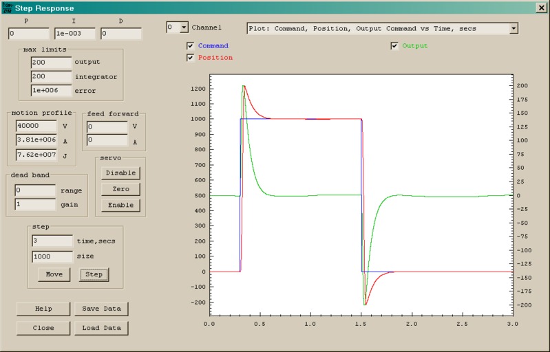
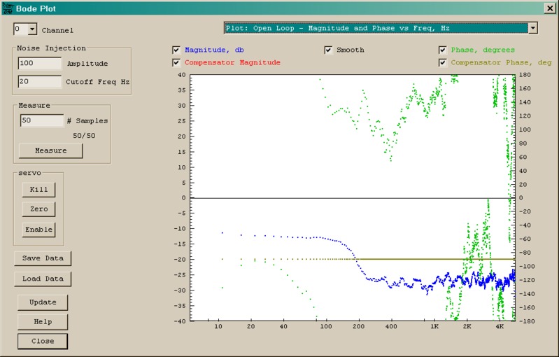
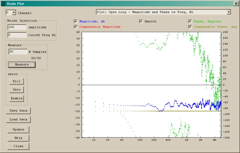
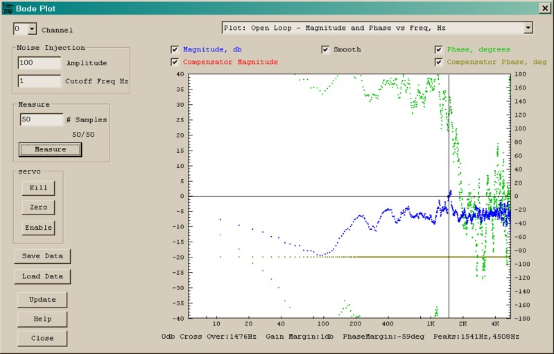
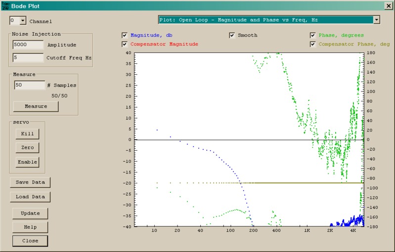
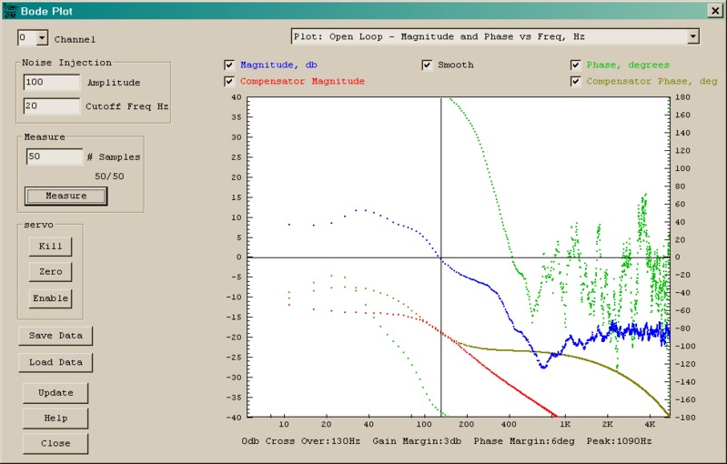
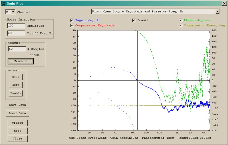
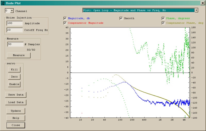
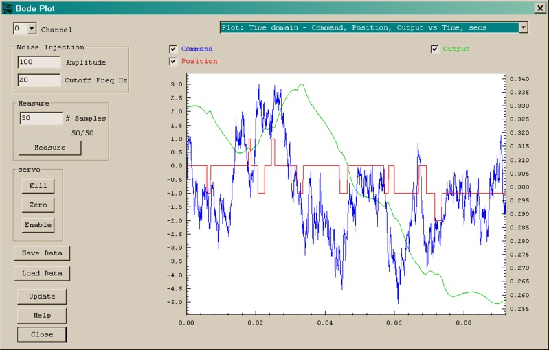
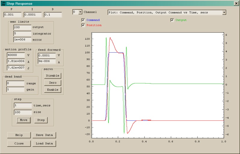
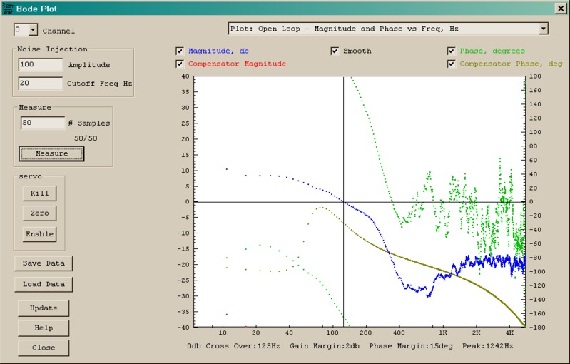
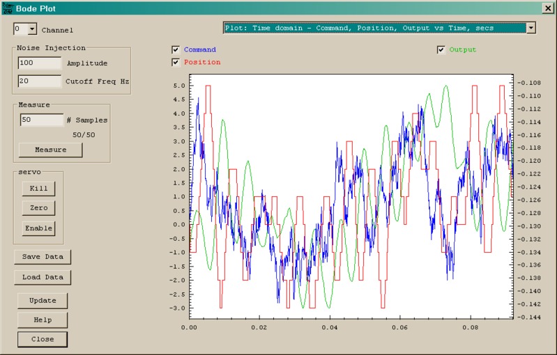